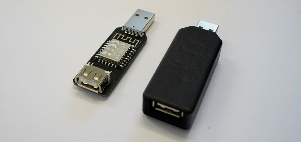
USP
A USB smart plug designed to be hackable and easily modified.
Powered by an ESP8266 and a tiny yet powerfull IRLML2502 single N-Channel mosfet. It can measure its supply voltage via the ESP’s ADC and comes in a rugged matteblack nylon & glaß compound case manufactured on a Formiga P110 industrial 3D-printer.
What can i use it for? What is it compatible with?
First of all lets start with the most important question, what is it for? That question is easily answered, it is a IoT device for turning on or off USB appliances. Take for example decorative lights, ive got a few of them in my room and i have to turn them off in order to sleep, but then the next day i have too turn them back on again, if i want them too look nice. Wouldnt it be great for that to happen automaticaly each morning and evening? Or in combination with your smart home controlled room light? Thats what the USP could be for, or those plant lights? Since it is simply a ESP it also is compatible with about everything your everyday ESP8266 developement kit would be compatible with! ESPhome, tasmota, you name it.
But what are its specifications and ratings?
As mentioned, the USP utilizes the fairly common IRLML2502 N-Channel mosfet so at 5V you can pull up to 3A easily, PD charging is only possible up to 9V since the ESP gets its 3.3V of an AMS1117 linear voltage regulator, therefore the 215mA for our ESP limits the input voltage down to said 9V maximum, if you want to use it in a usecase where the input Voltage surpasses this limit you have to throttle the power consumption of the ESP proportionaly to the voltage. If youre not totaly sure what youre doing we recommend to never exceed 9V (this allows for light Power delivery, but again, be carefull PD > 9V can easily kill your device in a matter of minutes or seconds). Temperature wise the USP can easily take everything a human can, though it is not waterproof and only splash proof at best. If exposed to very hot temperatures and maybe direct sunlight please stay with regular 5V USB power. In terms of range, the ESP can connect to your router just as well as your ESP-devkits can so for IOT applications in your home it should be sufficient.
Modifiability
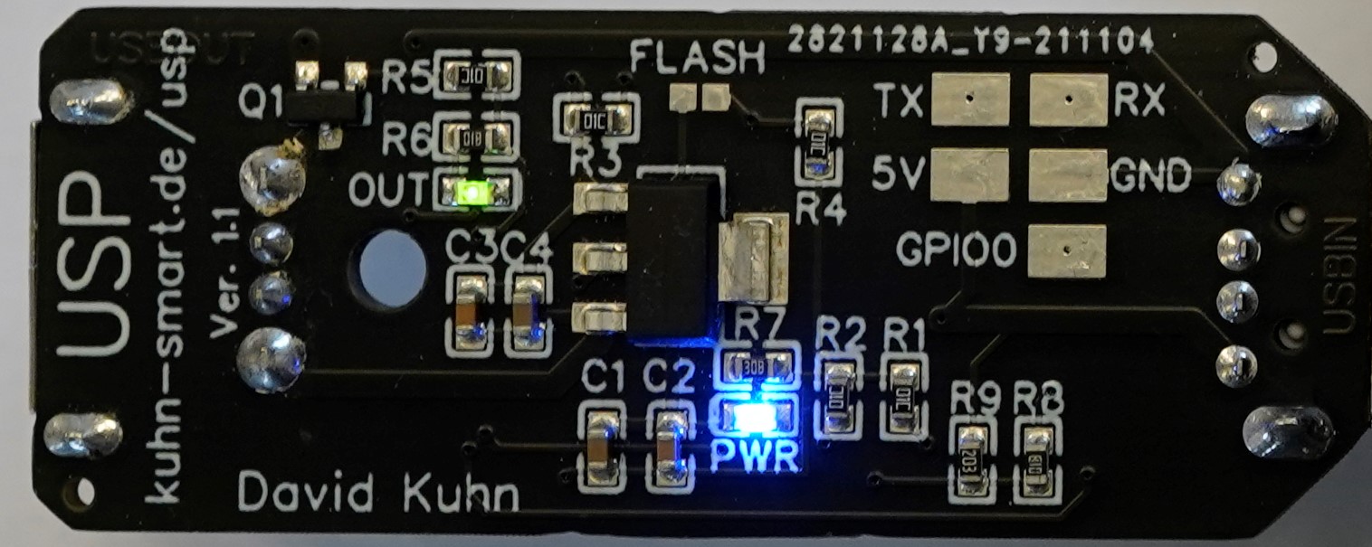
As already mentioned the USP’s modifiability is one of its strong points. It comes pre loaded with an OTA program so you dont even have to use an FTDI flasher to upload your first binary. If you wish to connect to its serial interface however, that to is made easy. There are five 2x3mm solderpads on the back for you to connect to (TX, RX, 5V, GND, GPIO0). Theres also a solderbridge labeled „FLASH“ that when closed pulls down GPIO0 (Note that under normal operation it has to be open).
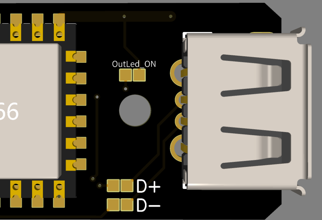
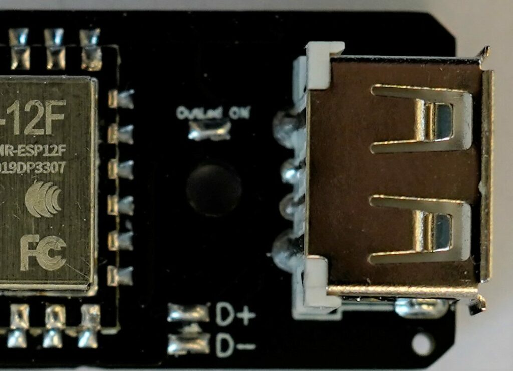
On the top side, in between the ESP8266 and the USB outlet the USP features three more solderbridges. The ones labeled „D+“/“D-“ are used to connect or disconnect the USB data lines. „OutLed_ON“ however is for activating or deactivating the „OUT“ indicator LED
Setup Guide
First of all you need to make yourself a software binary that you want to flash onto your USP. This binary can later be flashed onto your USP using its OTA program. However you can also use an FTDI programmer (just shop for „FTDI programmer“ if you dont already own one ) to use the tasmotizer for example.Though as long as you can compile the program into a binary it is possible to flash it onto your device without even having to solder a single wire.
OTA
In order for you to flash your device „Over-the-air“ you will ned two things: A device capable of connecting to the USP’s wifi hotspot and a precompiled binary . Your uploading device can be a Laptop or a wifi capable desktop PC. We do not recomend using your phone, due to reliability issues.
Your USP’s hotspot should show up as: „USP Ota Hotspot“. It is not password protected. If you succesfully connected to youre USP you can now either head to its IP or just simply to: „http://usp_ota.local/“ in your browser. Now you should see three fields, two for your Wifi SSID aswell as your pasword and one for a binary to flash onto the Chip. Do not enter your wifi credentials, this method doesnt work reliably and is very unsafe. Instead go to the OTA field to upload your .bin file. As soon as you have uploaded the file and reloaded the site, wait about a minute for it to install and restart. If the Upload was unsuccesfull, try repowering the device and If that doesnt work please procede to the FTDI method. However if you’ve done everything as mentioned and your Binary is working, the device will do as told in its new firmware.
If something goes wrong in this procedure, it can easily brick the software in your device, but dont worry, you can easily recover it, by just using the FTDI method.
FTDI
As mentioned multiple times already, the USP can be treated like a 8266 devkit and is therefore easily flashable via UART. All you have to do is connect the solder pads of the USP to your FTDI programmer. RX to TX, TX to RX, 5V to 5V and GND to GND. In order to get into flash mode you have to either close the „FLASH“ solderbridge, or pull „GPIO0“ down (Connect it to „GND“. That also is preciseley, what closing „FLASH“ does). Then use your flashing software of choice, we recommend the ESPHOME-FLASHER for its simplicity and reliability. Select your binary and COM port (If you have multiple COM devices shown, just disconnect your FTDI & USP combo to see which one disapears). Once seraial-port and Firmware are selected you can hit „Flash ESP“ and wait for the process to be done.
Speaking about „.bin“ files and code:
The software
The USP was developed with Home Assistant (HassIO) in mind, though that doesnt mean you cant use it with other ESP8266 compatible softwares like Tasmota for example. In this case there is a working code for ESPHome which is available as an integration for Home Assistant.
ESPHome YAML
Code:
# Set a device name, it will be the name of the device and the name of its
# Sensor, switch & Hotspot (only lowercase letters & numbers). For example:
# Device name: usp_3  Then the switch will show up as: usp_3 USB-OUT
# and the input voltage sensor will be: usp_3 Input Voltage
# and the Fallback Hotspot: usp_3 Fallback Hotspot
# it is by default set to: kuhnsmart_usp, do not hesistate to change it ;-)
substitutions:
  device_name: kuhnsmart_usp

esphome:
  name: ${device_name}  # <--- your device_name will be inserted here.
  platform: ESP8266     # <--- Type of device and board. Already set for the USP
  board: esp01_1m       # <-----------------------------------------------------


wifi:
  # Insert your WIFI credentials here:
  ssid: "WIFI"  # <--- The SSID (your WIFI's name)
  password: "PASSWORD"  # <--- The coresponding password


  # Enable fallback hotspot (captive portal) in case wifi connection fails
  # Please insert a Password for the Fallback hotspot.
  ap:
    ssid: "${device_name} Fallback Hotspot"
    password: "Hotspot password"  # <--- Insert Hotspot password here


# Enables you to control/check its LOGS from: "http://device_name.local/"
web_server:
  port: 80


# Enables the fallback hotspot in case it cant find the WIFI for 1 minute.
captive_portal:


# Enable logging
logger:


# Please insert an API password, it will be required -
# when connecting to the Usp via the Home Assistant API.
api:
  password: "APIpassword"


# Please insert an OTA password, it will be required -
# when uploading new software files via OTA.
ota:
  password: "OTApassword"


# This switch function is responsible for switching the onboard mosfet of the USP.
# the mosfet is active when high and connected to gpio14
switch:
  - platform: gpio
    pin: GPIO14
    name: "${device_name} USB-OUT" # <--- if you want a different name
                                   #      for the switch change it here.


# The sensors readout is a Measurement of the USPs input voltage.
# the voltage devider is connected to the ESPs internal ADC (pin A0 / ADC0)
# its Updated every 10 seconds. Do not change the multiplier, or your
# values will be wrong.
sensor:
  - platform: adc
    pin: A0
    name: "${device_name} Input Voltage"  # <--- if you want a different name
    update_interval: 10s                  #      for the sensor change it here.
    filters:
      multiply: 21                        # Multiplier, needed to get from the
                                          # ADCs raw measurement to usable Value
                                          # DO NOT CHANGE
The pinout
If you want to utilize a different software or write your own code, you can do so, this is the USPs pinout:
The mosfet for turning on the USB-OUT power on: GPIO14, active when pulled high
The voltage divider for reading the input voltage: ADC0/A0
The value received from the adc is one twenty-oneth of the actual input voltage, so it has to be multiplied by 21.
Where to buy?

Did we forget something you wanted to know? Do you have any questions or ideas? Dont hesistate to contact us at: info@kuhn-smart.de!